5. The OT window
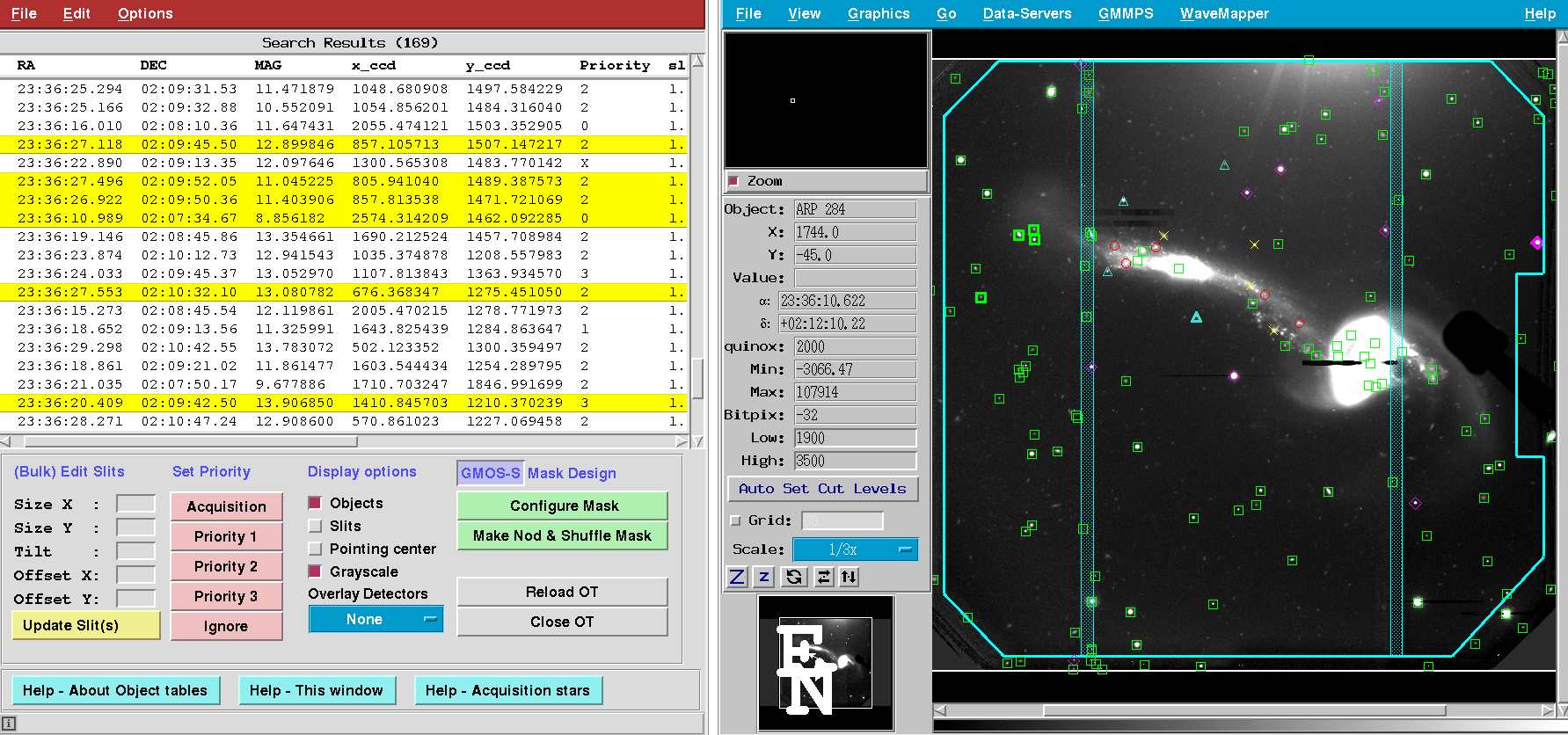
Fig. 5.1 The OT window (left) allows you to interact with the targets. You may change slit geometries and priorities. Detector gaps (for GMOS) and the area where slits may be placed (cyan polygon) are shown in the Image window (right).
5.1. Loading OTs
Warning
The ASCII (*.cat) OT tables are temporary files and may be overwritten on the fly at any time and without warning. They use a specific (undocumented) syntax that is very easily corrupted by tabs, blanks or any other string of characters, even in what might appear as a comment section. By all means, leave them alone.
5.2. Editing OTs
The OT FITS table can be easily edited in the OT window (Fig. 5.1). No external FITS table editor is required. Your changes are immediately visualized in the image overlay.
Using Shift-Click or Ctrl-Click you may select multiple objects directly in the OT window for bulk editing. Objects selected will be highlighted in the image window. Likewise, the same can be done in the image window, which will highlight the selected objects in the OT window.
For example, to adjust the slit geometry you would:
Select the object(s) you want to edit. To select multiple objects in the OT window, either do Shift-Click for a block of successive objects, or Ctrl-Click for non-successive objects. The latter also works in the image display where the objects are visualized.
Enter the desired new parameters, such as slit length (SIZE_Y for GMOS, SIZE_X for F2) or the slit width. You may change more than one parameter for more than one object at the same time.
Click the yellow Update Slit(s) button to make your changes. In case of many rows this may take a few seconds. If you just want to change a single parameter, you may also hit Enter instead. Note that this will update only the parameter that currently has the focus.
Note
From within GMMPS you cannot save any edits made to the OT FITS table. You must move forward with the mask design (“Configure Mask”). If you want to edit the OT permanently, or have a substantial numbers of edits to do, use external FITS table editors prior to GMMPS.
5.2.1. External FITS table editors
Consider the following FITS editors when it comes to substantial editing of the OT:
Fv http://heasarc.gsfc.nasa.gov/ftools/fv/
Topcat http://www.star.bris.ac.uk/~mbt/topcat/
IRAF tables.ttools
Both Fv and Topcat can be used to quickly edit FITS tables, add new columns, and do calculations on them. While Fv also offers some basic plotting capabilities, Topcat is a powerful tool to visualize data sets and interact with them. For more information about IRAF’s table editing tools type help ttools.
5.2.2. Edit Menu
To edit any other column of a single object, choose Edit -> Edit selected object… from the main menu. This will bring up the dialog below. Using the same Edit -> … menu you may also remove objects from the OT or add new ones.
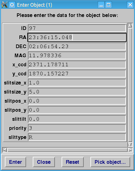
Fig. 5.2 The dialog window to edit individual object entries.
5.3. Set Priority
5.3.1. How to prioritize
Objects in the OT need to be prioritized. Priorities can be edited like any other slit parameter. You may also select one or more targets in the OT or the image window, and then click on the desired pink priority button.
There are five priority levels:
priority = 0: Acquisition star
priority = 1: Highest priority
priority = 2: Medium priority
priority = 3: Lowest priority
priority = X: Ignore Object
Acquisition stars are used to align the mask on the sky. Priority 1 objects are the ones that you wish to observe. Priority 2 and 3 objects are potentially interesting, however at this time slits for them are less important. GMMPS will place as many priority 1 objects in a mask as possible, then fill the remaining space with priority 2 and then priority 3 objects. Targets that you want to keep in the OT but ignore for the time being have priority X.
More information on how GMMPS uses priorities.
Note
At least two acquisition stars are required for mask alignment, and three are recommended. Mask designs based on pseudo-images must use at least three acquisition stars. Add a fourth star if you are uncertain about one of them. More than 4 acquisition stars are not recommended and will lead to excessive overheads.
5.3.2. Visualizing different priorities
Priorities are visualized by different symbols.
The default plot symbols are:
Acquisition = Purple diamond
Priority 1 = Red circle
Priority 2 = Green square
Priority 3 = Cyan triangle
Ignore = Yellow cross
This can be configured under Options -> Set Plot Symbols… from the main menu, displaying the following dialog:
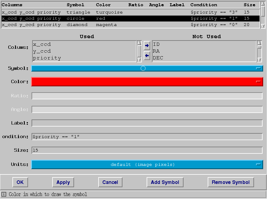
Fig. 5.3 Each priority level has a different symbol that can be configured by the user. Here priority 1 objects are associated with a red circle.
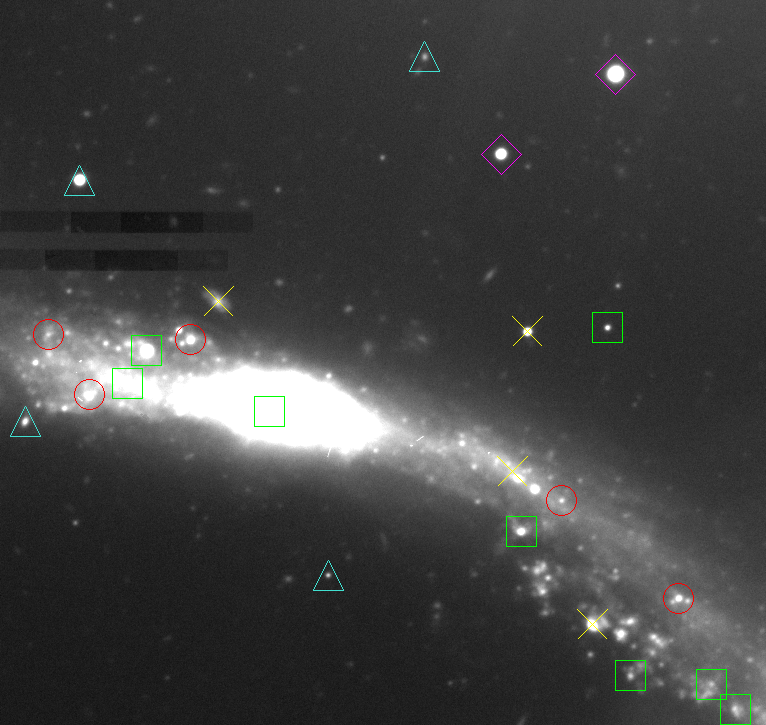
Fig. 5.4 Default plot symbols for objects with different priorities.
5.4. Display Options
Various overlays may be toggled on/off in the image window:
Objects: Displays the objects in the OT. They are plotted based on their (RA,DEC) coordinates. If you want to select an object in the image window, this option must be ON.
Slits: Displays the slits with their correct geometry. They are plotted based on their cartesian (x,y) coordinates. You may need to toggle this off/on to update the visualization after a change to the table was made. Remember that this is before the mask design, hence a lot of conflicting slits whose spectra would overlap may be present. Note that you cannot select an object by clicking on a slit. To this end the Objects display must be switched on.
Pointing center: This corresponds to the (RA,DEC) you must specify in the phase II observations (corresponding to your pre-imaging data). Actually, what is plotted are the CRPIX1/2 coordinates in case of pre-imaging, and the image center in case of a pseudo-image (which may have its CRPIX1/2 at wildly different locations).
Grayscale: Toggles between a grayscale image and the native Skycat color scheme.
5.5. Launching the Mask Design
Once you are done editing and prioritizing the OT, you launch the actual mask design process. For GMOS, you have the choice between Configure Mask and Configure Nod&Shuffle Mask, the latter requiring an intermediate step.
GMMPS can create several masks from a single OT.