6. Creating Masks (ODFs)
Once object priorities and slit geometries are set, you are ready to create Object Definition Files (ODFs). The ODF is the mask design you submit to Gemini.

Fig. 6.1 The mask configuration window. The graphics in the upper right shows the total system throughput (grating, filter, detector, atmosphere; neglecting optics for GMOS) for the chosen configuration. The thick blue line is normalised to the peak throughput of this combination, whereas the thin gray line displays the absolute throughput. It also displays the central wavelength (CWL) for this throughput curve, from which you may deviate. The summary window at the bottom displays the number of objects selected per mask and per priority after the slit selection algorithm was run.
6.1. How to create an ODF from the OT
Click on the Configure Mask button in the OT window. If an acquisition star is too close or within a detector gap, or too close to the border of the slit placement area, an error will be reported. Remove the object from the OT, or change its priority. GMMPS will inform you about potential order overlap and performs other consistency checks.
If the acquisition stars are ok, the Configure Mask button will bring up the mask making window shown above. There are two categories of parameters, Instrument Setup and Slit Placement, described below. GMMPS will remember the settings made and replay them next time you make a mask.
Under Instrument Setup you choose:
Central wavelength is user-defineable for GMOS. GMMPS will automatically pick the CWL that corresponds to the center of the total throughput curve. Of course you may deviate from this within certain limits (Sect. 6.2). For F2 the central wavelength is fixed, determined by the grism/filter combination.
Under Slit Placement you set:
Auto Expansion: This mode will expand all slits placed in a mask to maximize the amount of sky covered by each slit. This is an asymmetric process, and targets will not be centered along the slit afterwards. Auto expansion is not available for micro-shuffling mode (Sect. 7.2).
Pack spectra: If the grating / filter combination results in short spectra, then GMMPS will place two or more slits in the dispersion direction (only if the spectra do not overlap; see Sect. 6.4).
Minimum separation defines how many pixels should be left between the spectra. Default is 4 pixels, which is sufficient for software to automatically recognize the various spectral footprints.
Wiggle amount [%]: The percentage by which GMMPS may decenter the slit with respect to the object, to maximise the number of slits per mask. The upper limit is 50%, meaning a displacement by half the slit length (which will truncate the object, so perhaps stay a bit below that number). Wiggling is not available for micro-shuffling mode (Sect. 7.2).
Number of Masks: How many ODFs (masks) will be created from this OT. If more than one mask is made, then each mask will include the maximum possible number of priority 1 objects, with lower priority objects filling any spaces. The following mask will not include any objects used in the prior masks, except for acquisition stars, which will be included in all masks.
Click on Make Masks to run the slit placement algorithm. If you have already created a mask for the current image, GMMPS will warn you that the mask name already exists. You may then enter a new filename (without the ODF.fits extension) or select an existing ODF FITS from a file dialog. This task also downloads the proper motions of the acquisition stars as tabulated in the PPMXL catalog from the CDS server in France. If the proper motion in any direction (RA or DEC) is higher than 100 mas/yr, then a warning will be shown. If it is higher than 250 mas/yr, the task returns with an error. In this case, you must remove the offending acquisition star from the mask design.
Verify the masks (load the ODFs). If you are not satisfied, you must go back and edit the OT. However, be sure to close all mask making windows first.
Note
The position of the slit center is calculated as (x_ccd + slitpos_x, y_ccd + slitpos_y).
If any priority changes are required, then you must close all mask making windows first. Otherwise any changes made in the OT window are not recognized by the already-open mask making windows.
6.2. Choosing the right CWL for GMOS
The CWL is updated every time you choose a different grating and / or filter. GMMPS will default the CWL to the center of the total throughput bandpass. That means that for a slit near the detector center the spectrum will have equal extents to the left and to the right of the slit. The anamorphic factor will skew this for slits in the left and right half of the GMOS detectors. Check out Nick Konidaris’ instructive webpage about anamorphism in spectrographs.
Most likely you will deviate from the default CWL setting. For example, the total width of the throughput curve may not fit onto the detectors at the same time, and / or you are more interested in the bluer or redder sections of this bandpass. Also, spectra closer to the detector edges will be truncated in wavelength more than others.
6.3. Internal consistency and safety checks
GMMPS performs a number of checks before placing slits on a mask, and informs you accordingly:
If the CWL is chosen very asymmetrically with respect to the transmitted bandpass, pushing the spectra to either side of the detector.
If the chosen grating / filter combination is highly inefficient, and another combination offers much higher throughput
If order overlap occurs within spectra, including information at which wavelengths this happens. Order overlap can be visualized in the ODF window to decide whether or not an order sorting filter is required.
If order overlap occurs between packed spectra, i.e. 2nd orders of one spectrum overlap the first orders of another spectrum located in dispersion direction (see below).
6.4. Packing spectra
GMMPS tries to place as many slits as possible in a single mask. If the grating / filter combination produces short spectra, then two or more spectra may be placed next to each other in dispersion direction without overlapping (“packing”).
This is the default mode for all GMOS and F2 configurations. With GMOS, many configurations produce short spectra. In case of F2, packing will only occur for:
R1200_JH grism with Y, J, or H filters (as compared to the default JH wide filter)
R1200_HK grism with H, K-short, K-long, K-red, K-blue filters (as compared to the default HK wide filter)
The advantages are obvious, as up to several hundred slits can be placed in a single mask if one is interested in a small spectral region, only.
6.4.1. Caveats in packed mask designs
Masks with packed spectra present a few (mild) disadvantages, and therefore packing can be turned off (GMMPS v1.4 or later).
Footprint detection: The Gemini IRAF reduction package (in particular, the gscut task) may not fully automatically detect the spectral footprints for packed mask designs. Manual intervention might be required (GMOS and F2).
The following caveats apply to GMOS, only.
Uneven sky coverage: If two spectra can be placed next to each other, then GMMPS will place more slits to the left and the right, on the expense of slits in the center (assuming equal priorities). If more than one mask is designed from the OT, then this will continue until the targets at the sides have been depleted. No such asymmetry will arise if three or more spectra can be placed next to each other. For F2 this is not an issue because of the relatively small extent of the slit placement area in the spatial dimension.
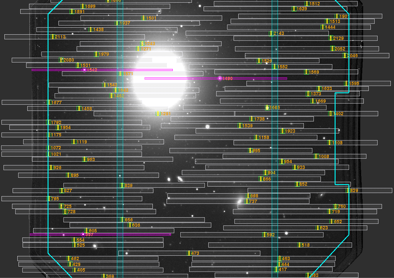
Fig. 6.2 Packing occurs if more than one spectrum can be placed in dispersion direction. In case of two spectra, asymmetric sky coverage may occur in case of equal priorities (in this case, the R400 grating and the z+CaT filter combination).
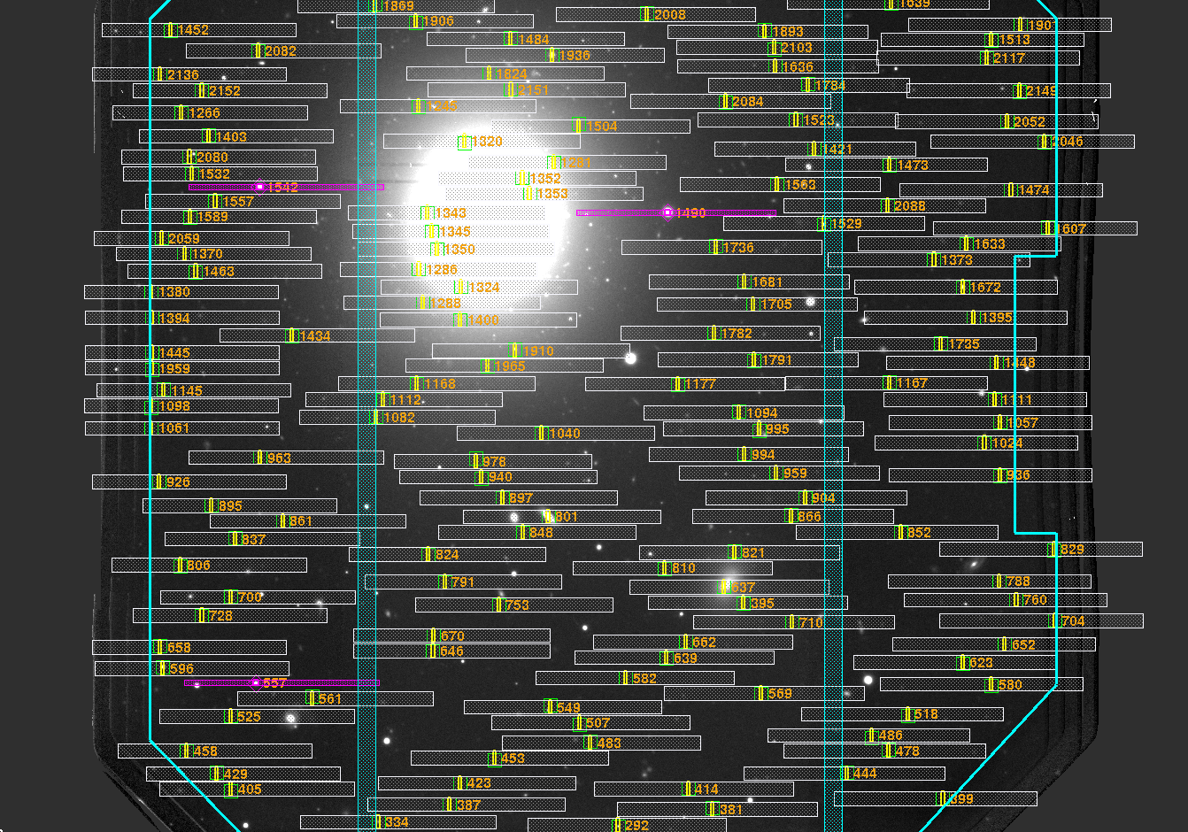
Fig. 6.3 A more even sky coverage is achieved if three or more spectra can be packed (R150 grating, r filter).
Second order overlap (R150, only): The second orders of the slits in the right half of GMOS may overlap the first orders of the slits in the left half of GMOS. This occurs almost exclusively for the R150 grating, only. As the second orders of the R150 are faint (on the order of 1% of the first order), this is of little concern for many application and the order overlap may be ignored. The only other scenario where this occurs is for the R400 grating in combination with the g-filter, a rather insensitive combination where minimal overlap occurs.
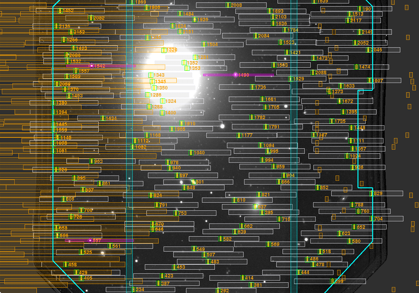
Fig. 6.4 Order overlap for the R150 and r filter: The 2nd orders of the slits in the right half of GMOS overlap the first orders of the slits in the left half (large orange spectra). The zero-th order of the left slits overlap the first orders of the right slits (compact orange spectra).

Fig. 6.5 Order overlap for the R150 and z+CaT filter: The order overlap by second and zero orders decreases for redder bandpasses.
Note
Order sorting filters do not necessarily help here as they reduce overlap between 1st and 2nd orders of the same target, but not between different targets. The effect is less pronounced for redder bandpasses.