13. Appendix: Mask check instructions
Below are the step by step mask check instructions for NGOs, PIs and Gemini staff.
13.1. Summary
Check ODF for correct naming convention (critical)
Targets in the slits (critical)
-
2-3 for pre-imaging, 3-4 for pseudo-images (critical)
Must not saturate in image (critical)
Should be well distributed (warning)
Should be stars, not galaxies (warning)
Should be bright enough and ideally within 2 magnitudes of each other (warning)
Must stay clear of edges and chip gaps (enforced by GMMPS)
-
RA, DEC, position angle, nod&shuffle offset same in ODF and phase II observations (critical)
Check for vignetting by the guide probe arms (critical)
Slits near edge of the slit placement area may not be cut (warning)
Slits must be within the slit placement area (enforced by GMMPS)
-
Slit length and q offset in the Observing Tool must be consistent with both nod positions (critical)
Nod & Shuffle offset (ODF window) and Offset (detector rows) (Observing Tool) must be identical (critical)
Nod & Shuffle masks using tilted slits must use a
 nod offset in the
Observing Tool (critical)
nod offset in the
Observing Tool (critical)Slits must not appear in storage bands (enforced by GMMPS)
Each science band must have the same height (enforced by GMMPS)
Two storage regions must be adjacent to each science band (enforced by GMMPS)
Storage area between science bands at least as high as science bands (enforced by GMMPS)
All slits in a microshuffle mask must have same length (enforced by GMMPS)
13.2. Before checking the masks
13.2.1. Naming convention
PIs must use the standard naming convention (example: GS2015AQ023-01_ODF.fits) when submitting their ODFs. Otherwise ask the PI to remove the masks from the Observing Tool and re-submit them with the correct names.
13.2.2. Obtaining pre-images and ODFs
Pre-images (and pseudo-images) for the mask designs are provided by the PI in the Observing Tool’s file attachment facility. Download the images together with the ODF FITS files using the Fetch button in the File Attachment window. The Observing Tool will ask for your NGO password. Verify that the PI put comments to either the ODF or the images that allow unambiguous association:
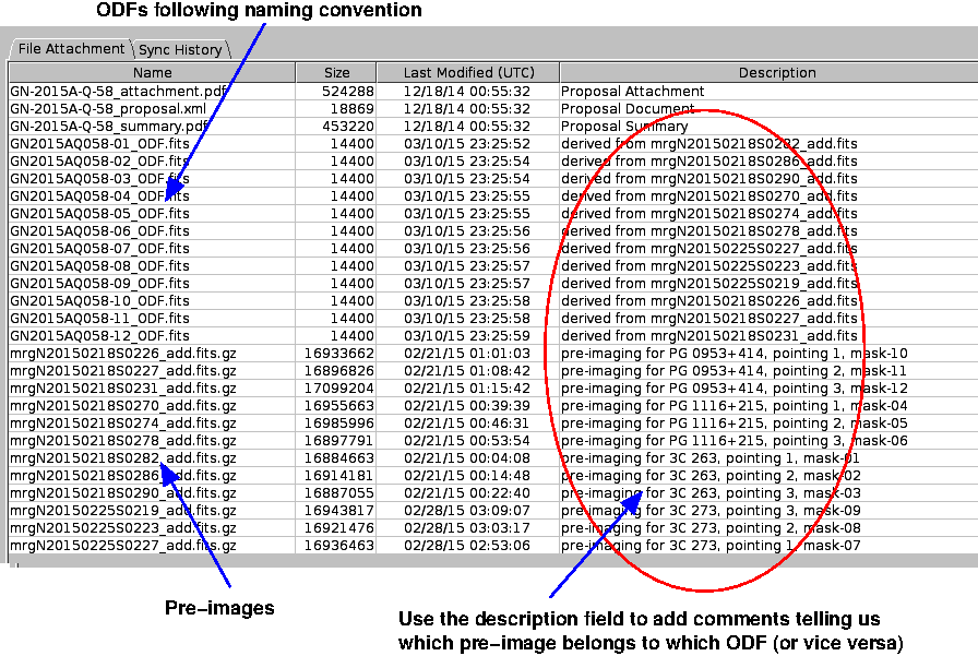
Fig. 13.1 The file attachment window. The “Description” field shows the name of the pre-images used to generate the masks.
13.3. Mask checks
13.3.1. Start GMMPS
Load the pre-image into Skycat, and adjust the dynamic range such that the image is displayed clearly.
Load the ODF FITS file, by selecting GMMPS -> Load Object Definition File (ODF *.fits). This will display the ODF window (see below) with all relevant information at your finger tips.
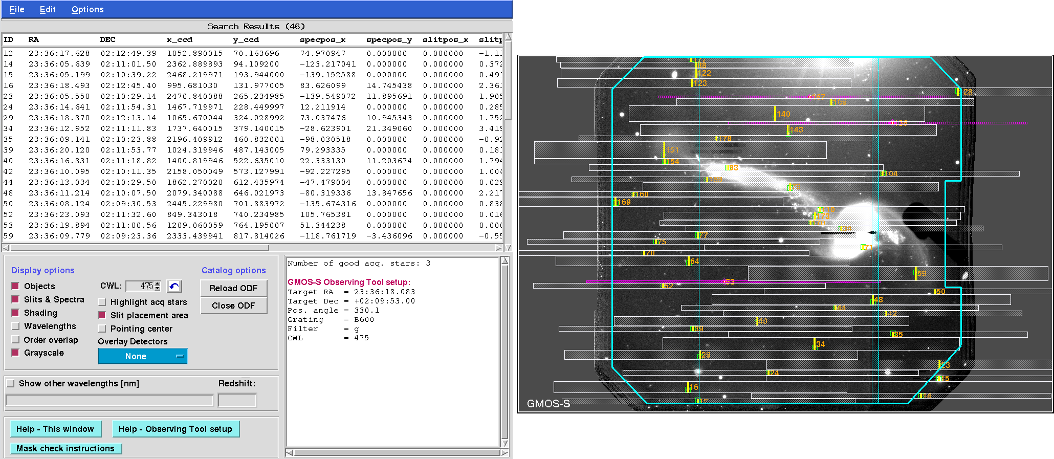
Fig. 13.2 ODF window
13.3.2. Slits
Switch on the Slits & Spectra overlay.
Checklist:
Targets inside slits: Check that the targets are inside the slits. In general they may not be centered along the slit, in particular if auto expansion was used to maximise the sky coverage, or slit wiggling to increase the number of slits per mask. In particular, pay attention to tilted slits (slittilt != 0 in the ODF window), which might e.g. be used to get two or more objects in the same slit.
Check the slit width: GMOS-N/S have long-slits with the following widths (normal and Nod & shuffle): 0.25”, 0.5”, 0.75”, 1.0”, 1.5”, 2.0” and 5.0”. For F2 these are 0.18”, 0.36”, 0.54”, 0.72”, 1.08 and 1.44”. If the width of the MOS slits is different, then inform the PI that for any required calibration (flux standard, radial velocity standard, etc) the closest matching long-slit must be chosen.
Slits near edge of slit placement area: Occasionally, slits within a few arcseconds of the border of the slit placement area may not be cut by the laser cutting machine. There is nothing that can be done about it.
Slits within slit placement area: Slits outside the cyan slit placement area will not be cut. Ask the PI why and how the ODF was modified outside GMMPS.
13.3.3. Acquisition stars
Click on Highlight acq stars in the ODF window. This will show the acquisition stars only.
Checklist:
Absolutely no saturation: Acquisition stars must not be saturated in the pre-image, otherwise their centroid cannot be determined well enough. This will directly affect the placement of the objects in the slits, and likely result in a flawed mask design. The same holds for pseudo-images, if the source positions are determined from the data that was used to build the pseudo-image.
At least 2 acquisition stars: There should be at least 2 (3) good acquisition stars for masks designed from pre-imaging (pseudo-imaging). The best masks are designed with 3-4 alignment stars. More than 4 acquisition stars are unnecessary and will significantly increase the overhead; excess stars should be removed from the mask design.
Well distributed: Ideally, acquisition stars should be several arcminutes apart. This may not always be possible.
Bright acquisition stars: Verify that the acquisition stars are bright enough (mag 14-20) for a 30 second exposure (common exposure time used for acquisition). The magnitude range (GAIA Gmag) is displayed in the ODF summary window.
Similar magnitudes: Acquisition stars should have similar magnitudes, ideally within 2 magnitudes. Otherwise the acquisition process could become compromised.
No galaxies: In principle, galaxies can be used to center the mask. However, the solution is inferior compared to stellar acquisition sources. This is an emergency solution only if no stars are available, and only permissible with pre-images (no pseudo-images) and for galaxies with a bright nucleus and without sub-structure. Ask the PI to replace galaxies by stars. If sufficiently many acquisition stars are available, eliminate the galaxies from the masks.
Stay clear of gaps and edges: GMMPS does not allow acquisition stars to be placed too close to the detector gaps and / or the boundary of the slit placement area. A warning will be issued in the ODF window if stars are getting close to the internal limits. Most likely they will be ok. A backup acquisition star must be included in the mask design unless there are already 2 (pre-image) or 3 (pseudo-image) other (good) stars present. Spectra of problematic stars will be highlighted in yellow (see example image below).
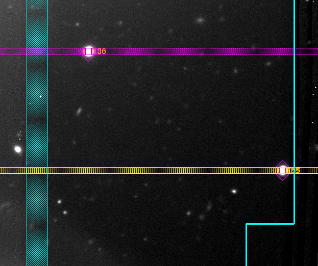
Fig. 13.3 Problematic acquisition stars. The lower right star is within 4.0” of the border of the slit placement area. Most likely this star is ok, but its spectrum is shown in yellow to flag it as potentially problematic. A backup acquisition star must be included in the mask design unless there are already 2 (pre-image) or 3 (pseudo-image) other stars present. The acquisition star to the upper left has a safe distance to the GMOS detector gap.
13.4. Nod & Shuffle masks
Nod & Shuffle masks have strict requirements, enforced by GMMPS. They can only be violated if the mask design has been modified outside GMMPS.
A band-shuffle mask consists of one or more science bands where slits may be placed, and adjacent storage bands. Slits in a band may have arbitrary length. In micro-shuffling mode, only one slit occupies a science band, and all slits must have equal length.
Checklist (all enforced by GMMPS):
No science slits must appear in the storage bands.
All slits in a microshuffle mask must have the same length.
Two storage regions must be adjacent to each science band. They must at least be as high as the science bands.
Each science band must have the same height.
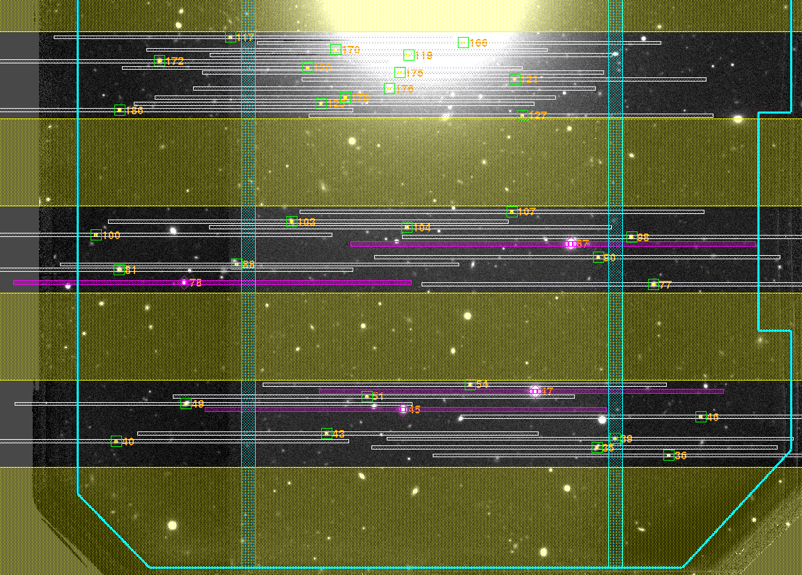
Fig. 13.4 This band-shuffle mask contains three science bands and four storage bands (yellow). The central two storage bands are shared between the adjacent science bands.
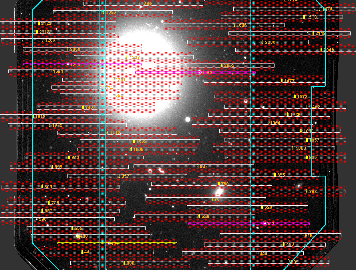
Fig. 13.5 This is a micro-shuffle mask. Each science slit has its own adjacent storage bands. Slits and spectra must not be located in the red storage areas.
13.5. Finalizing
Principal contact person:
If a mask has problems, contact the PI and explain the nature of the problem. Any critical problems must be fixed. Advise the PI to redesign the mask and resubmit it. To do that, the PI has to remove the previously submitted mask and upload the new ODF FITS file.
If the mask passed the quality control, “check” it in the File Attachment window (Check?) in the Observing Tool. An automatic e-mail notification is sent to
g(n/s)maskcheck [at] gemini.edu
g(n/s)qc [at] gemini.edu
Principal and additional contact persons.
On the Gemini side:
Once a mask has passed this stage, it will be double-check and converted to a format understood by the mask cutting machine. The mask is ingested into Gemini’s internal database and then scheduled for cutting. Once cut, the mask is outfitted with a barcode, mounted in a frame and transported to the summit, and notification emails are sent.
Once a mask is installed in the instrument, a mask image will be taken with a flat field source and the slits inspected for cutting errors. This is the final quality check. If persisting problems are encountered, the mask will be re-cut, or the PI will be asked to re-design the mask.
13.6. Phase II checks
RA, DEC, position angle: NGOs and Contact Scientists must check that RA, DEC, and position angle for a MOS observation in the phase II observations are identical to the values used to make the mask. This information is shown in the ODF window when displaying the spectra.
Guide stars: Check for vignetting. If placed inside the science field of view, the guide arm may shadow (a) an acquisition star, and (b) a significant number of slits, both of which may render the mask useless. Ideally, guide stars are chosen outside the field of view. Check with Gemini staff if uncertain.
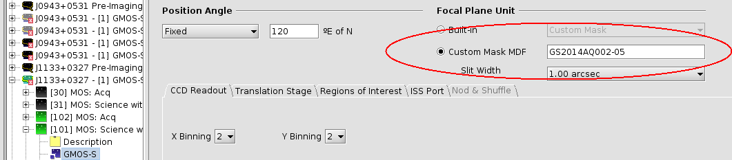
Mask name: The ODF root names with the mask numbers (e.g. GS2015AQ023-01) must be used in the field Custom Mask MDF in the GMOS static component of the corresponding observation in the Observing Tool:
GMOS static component with the correct mask name.
Nod offsets: Check that the slit length and the nod offsets in q-direction in the Observing Tool are consistent. For example, [p,q] nod offsets of [0,+10] and [0,-10] would be completely inconsistent with a slit length of 2 arcsec in a microshuffling mask (the objects would never appear in the slits, as they are placed above and below for both nod positions).
However, [p,q] nod offsets of [0,0] and [0,35] (in which case the telescope nods between the science target and a blank sky position), or nod offsets of [0,+0.5] and [0,-0.5] (in which case the telescope nods the target up and down within the slit) would both be compatible with 2.0 arsec long slits (see Fig. at the very bottom).
Nod offset for tilted slits: Nod & Shuffle masks using tilted slits must include a
nod offset, i.e. [0,0]. Otherwise, the object in question
will never be located in the tilted slit. GMMPS prints a warning for these masks
when displaying the ODF.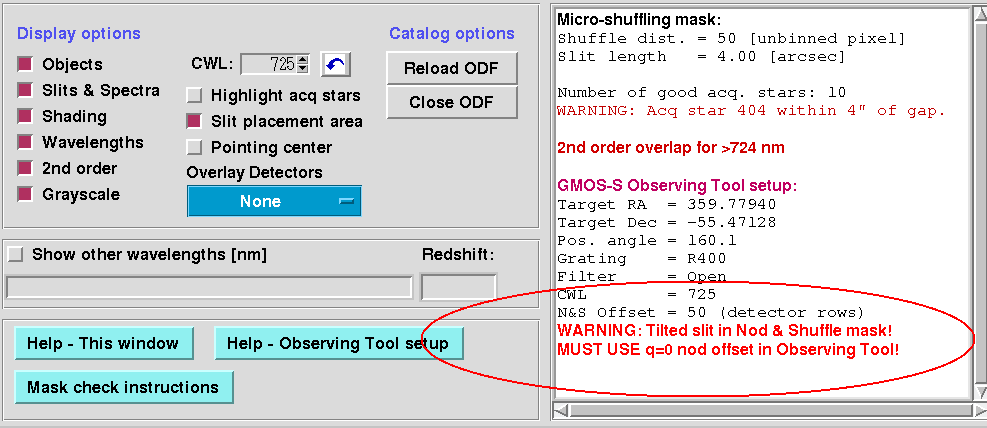
Fig. 13.6 A q=0 nod offset is required if tilted slits are used in a Nod & Shuffle mask. This mask also uses an unrealistically high number of acquisition stars (10).
Shuffle offset: Check that the Shuffle offset displayed in the ODF information window is the same as the Offset (detector rows) provided in the Nod & Shuffle window of the GMOS component in the Observing Tool.
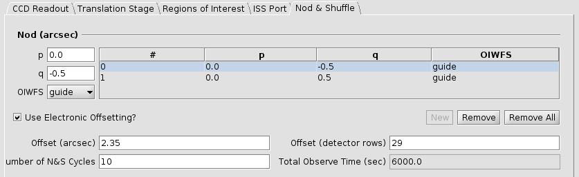
Fig. 13.7 Nod & Shuffle window inside the GMOS component of the Observing Tool. In this case, a nod distance of +/- 0.5” is good enough for a slit length of 2.0”. The shuffle distance (Offset (detector rows)) is 29.